| HOME | Dyna ST-70 | Dyna PAS-3 | Service & Mods | Downloads | Bookstore |
SP14 preamp 62 build photos
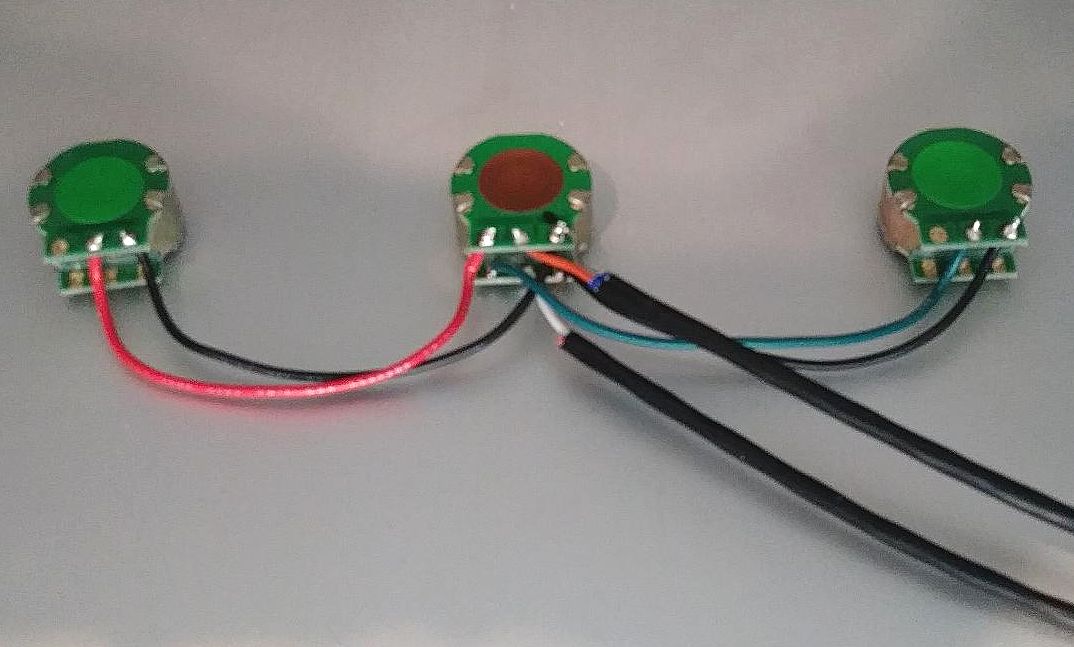
right attenuator (red wire), master attenuator (shielded coax out), left attenuator (green wire)
start with center terminals of master attenuator first, easier to wire the outside terminals afterwards
inputs to right and left attenuators shown in next photo
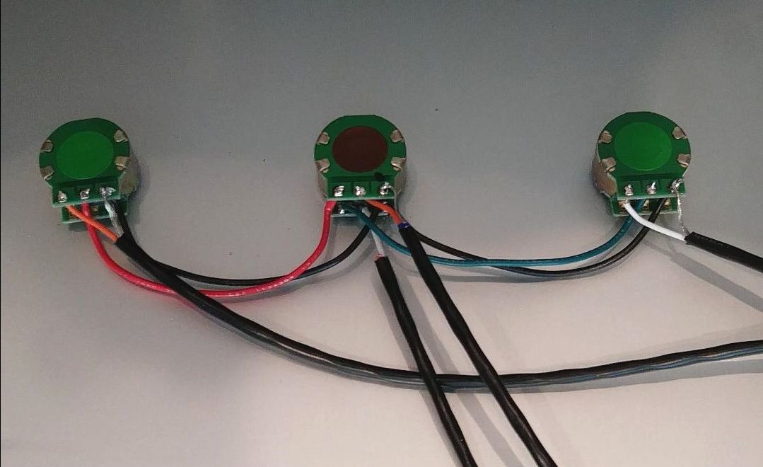 right and left outputs of TAPE-SOURCE switch (center terminals of switch) run to inputs of right and left attenuators
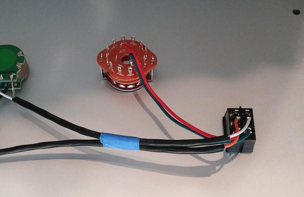 red wire is RIGHT output of selector switch to bottom terminal of SOURCE-TAPE switch
green wire is LEFT output of selector switch to bottom terminal of SOURCE-TAPE switch
 top terminals of SOURCE-TAPE switch are to TAPE-IN on rear panel (to be connected later)
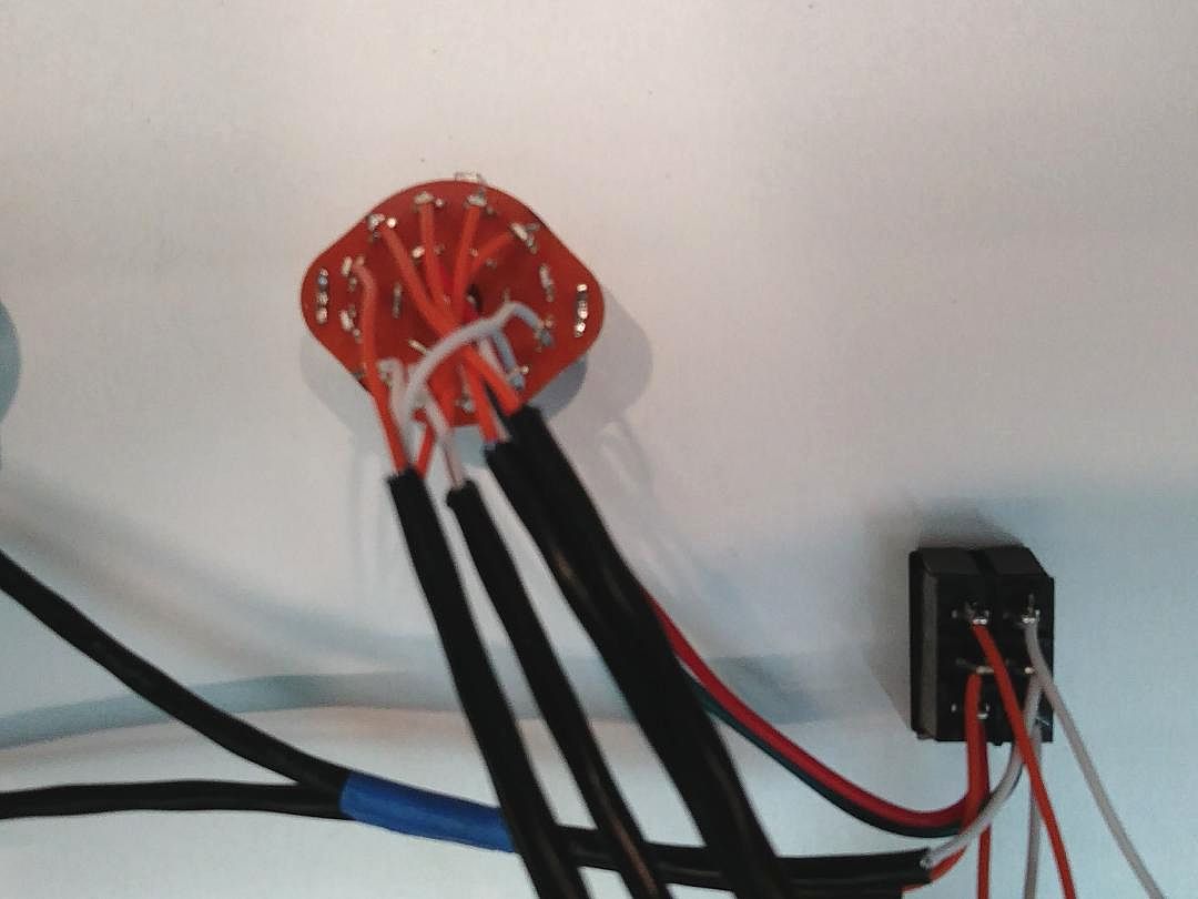
5 inputs to selector switch are wired (connected to rear panel RCAs later)
c
 front panel wiring all done
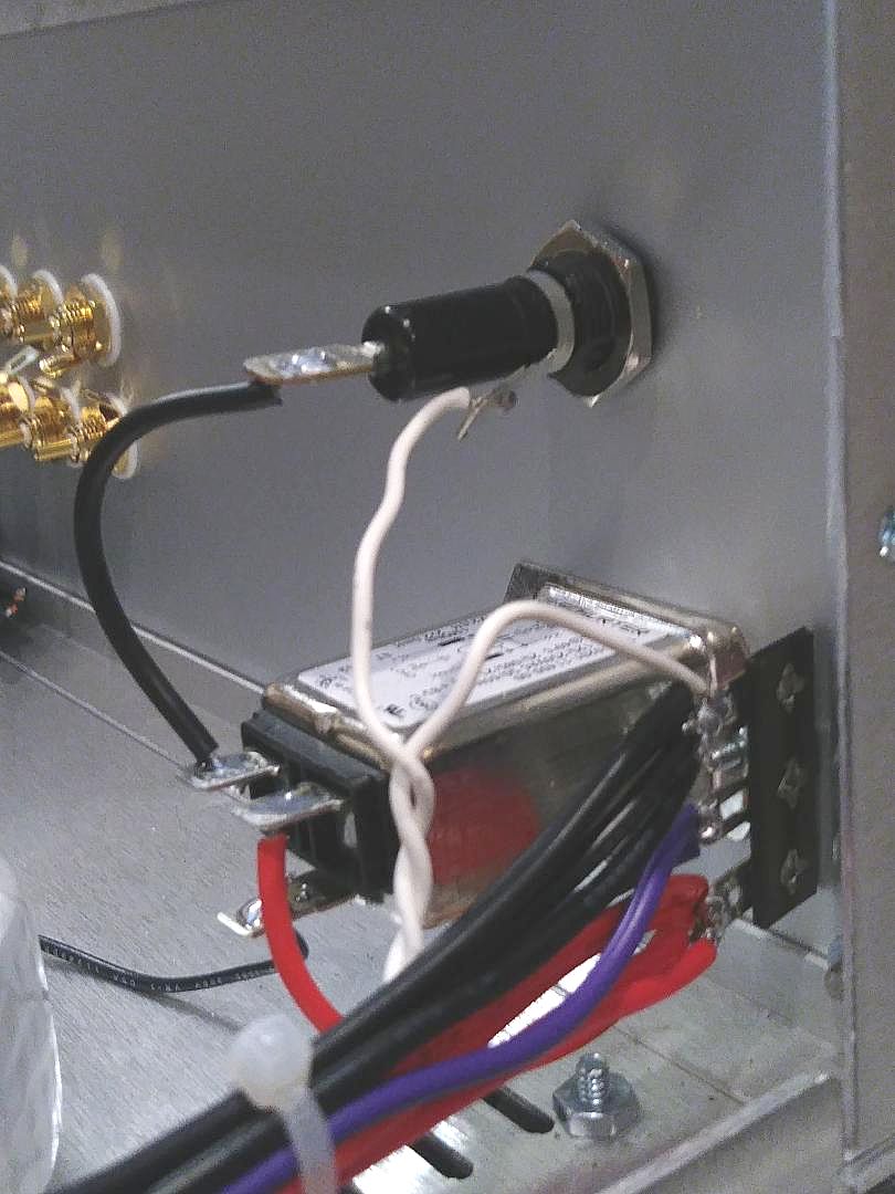 transformer AC connections to terminal strip
* connect all RED transformer leads to bottom lug of terminal strip next to AC input filter
* connect all PURPLE transformer leads to center lug of terminal strip next to AC input filter
* connect all BLACK transformer leads to top lug of terminal strip next to AC input filter
* take a 32" long white wire and use a drill to tightly twist a pair of wires to run from the front power switch to the rear fuse & terminal strip
* use a file to remove oxidation on fuse leads
* connect a short red wire from the neutral (N) side of AC input filter to the bottom lug of terminal strip
* connect a short black wire from the line (L) side of the AC input filter to the back of the fuse holder
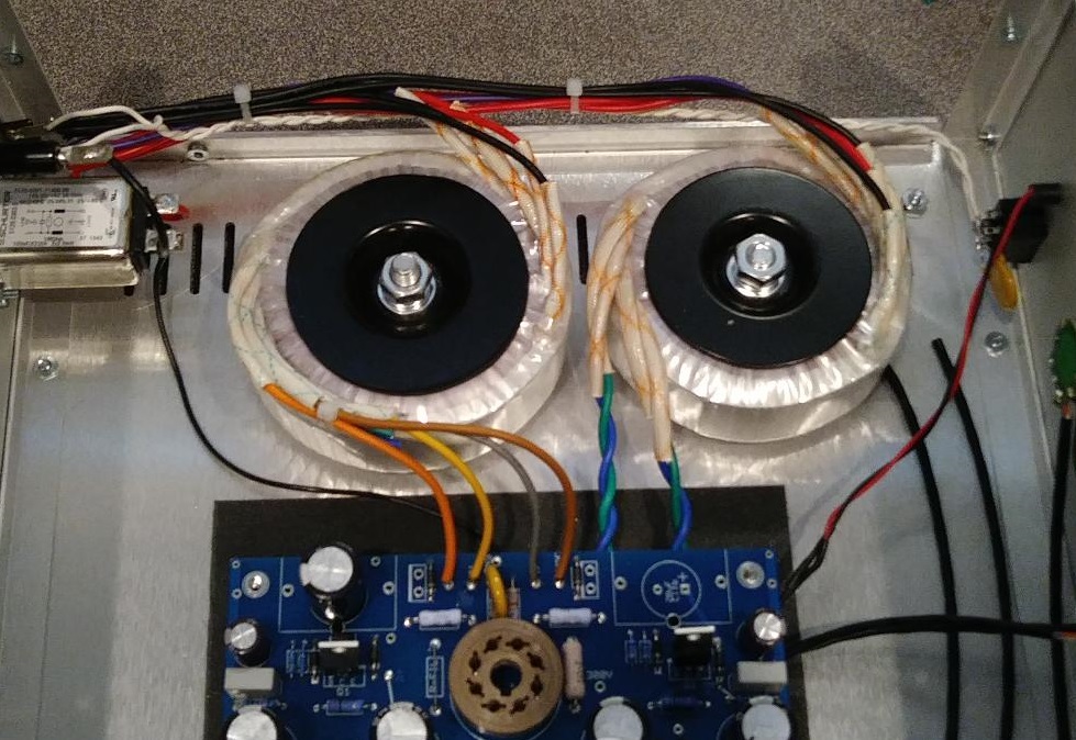 power transformer wiring to PCB
orange wire 6VAC - yellow wire HV - grey wire HV - brown wire 6VAC
power transformer wiring to PCB
orange wire 6VAC - yellow wire HV - grey wire HV - brown wire 6VAC
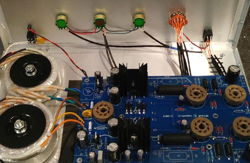
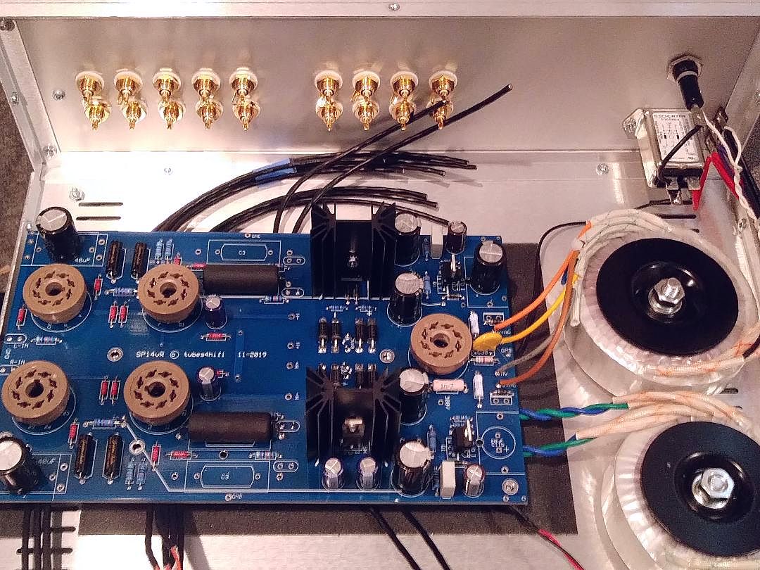
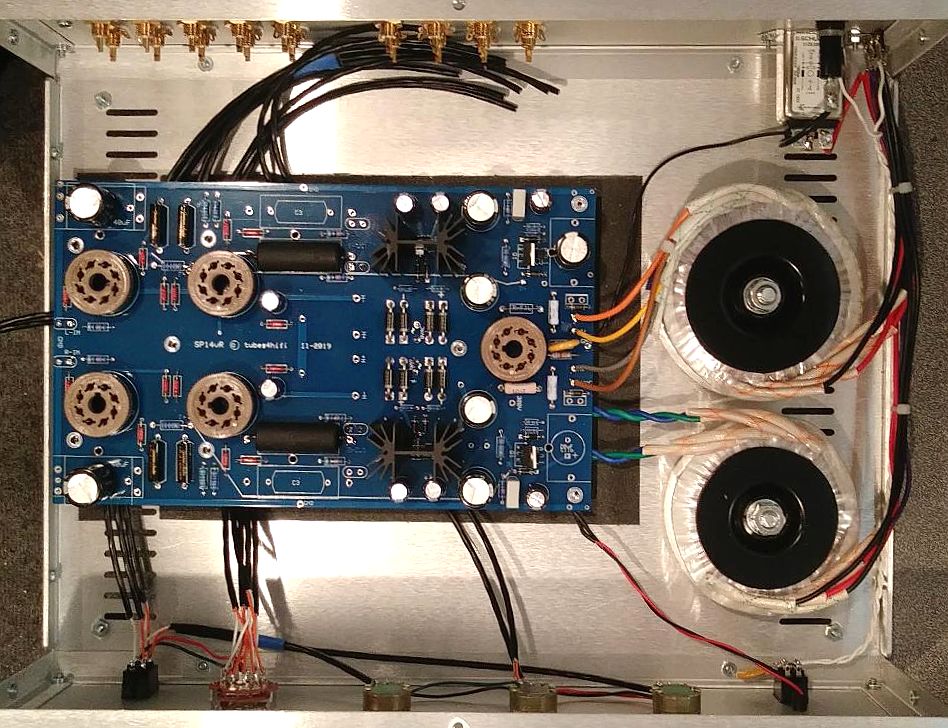 all wiring done except for rear RCA jacks
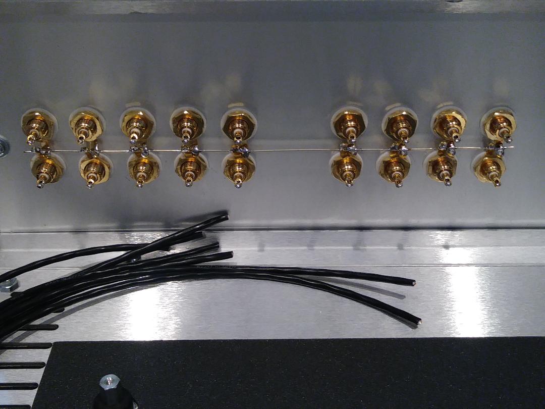
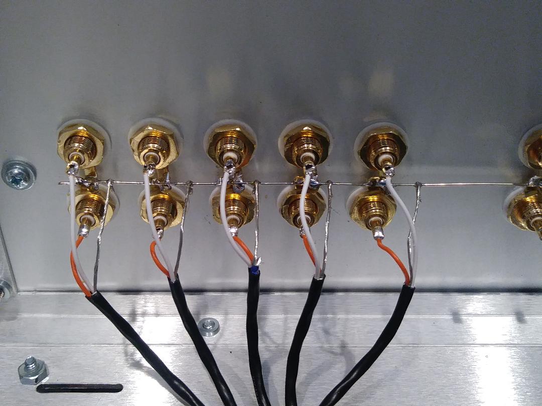
rear panel RCA ground buss
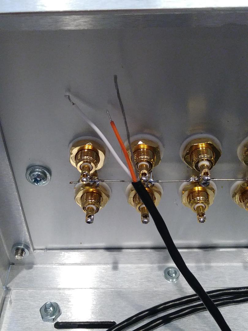
1st input pair from front selector switch, cut orange wire 1/4" than white and ground shield
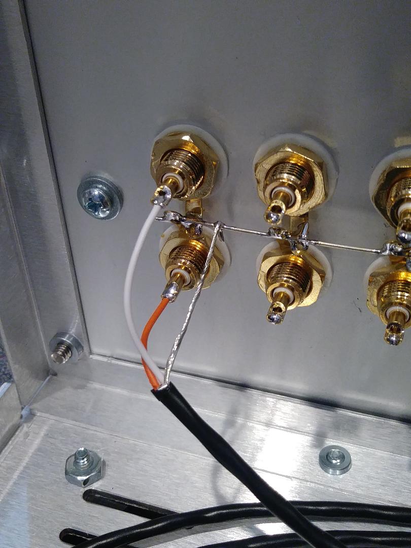
orange to 1st input right, white to 1st input left, and shield to RCA ground buss
all 5 inputs from front selector to rear RCA jacks and ground buss
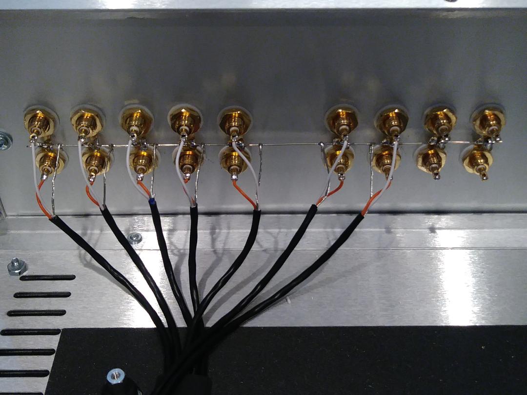
TAPE-IN and TAPE-OUT shielded cables connect to rear RCA jacks and ground buss
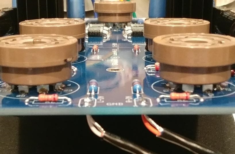
connect outputs from master attenuator to inputs of PCB (orange, right; white, left) and shield grounds
here are some photos to help you identify the parts to build the SP14
inquire about any other options or modifications you might want via email . . . .
send email to ROY at: info@tubes4hifi.com
right attenuator (red wire), master attenuator (shielded coax out), left attenuator (green wire)
start with center terminals of master attenuator first, easier to wire the outside terminals afterwards
inputs to right and left attenuators shown in next photo
right and left outputs of TAPE-SOURCE switch (center terminals of switch) run to inputs of right and left attenuators
red wire is RIGHT output of selector switch to bottom terminal of SOURCE-TAPE switch
green wire is LEFT output of selector switch to bottom terminal of SOURCE-TAPE switch
top terminals of SOURCE-TAPE switch are to TAPE-IN on rear panel (to be connected later)
5 inputs to selector switch are wired (connected to rear panel RCAs later)
c
front panel wiring all done
transformer AC connections to terminal strip
* connect all RED transformer leads to bottom lug of terminal strip next to AC input filter
* connect all PURPLE transformer leads to center lug of terminal strip next to AC input filter
* connect all BLACK transformer leads to top lug of terminal strip next to AC input filter
* take a 32" long white wire and use a drill to tightly twist a pair of wires to run from the front power switch to the rear fuse & terminal strip
* use a file to remove oxidation on fuse leads
* connect a short red wire from the neutral (N) side of AC input filter to the bottom lug of terminal strip
* connect a short black wire from the line (L) side of the AC input filter to the back of the fuse holder
power transformer wiring to PCB
orange wire 6VAC - yellow wire HV - grey wire HV - brown wire 6VAC
all wiring done except for rear RCA jacks
rear panel RCA ground buss
1st input pair from front selector switch, cut orange wire 1/4" than white and ground shield
orange to 1st input right, white to 1st input left, and shield to RCA ground buss
all 5 inputs from front selector to rear RCA jacks and ground buss
TAPE-IN and TAPE-OUT shielded cables connect to rear RCA jacks and ground buss
connect outputs from master attenuator to inputs of PCB (orange, right; white, left) and shield grounds
here are some photos to help you identify the parts to build the SP14
inquire about any other options or modifications you might want via email . . . .
send email to ROY at: info@tubes4hifi.com
|
| |
|
|