| HOME | Dyna ST-70 | Dyna PAS-3 | Service & Mods | Downloads | Bookstore |
SP14 preamp 2020 build photos
steps for connections
* connect all RED transformer leads to bottom lug of terminal strip next to AC input filter
* connect all PURPLE transformer leads to center lug of terminal strip next to AC input filter
* connect all BLACK transformer leads to top lug of terminal strip next to AC input filter
* take a 32" long white wire and use a drill to tightly twist a pair of wires to run from the front power switch to the rear fuse & terminal strip
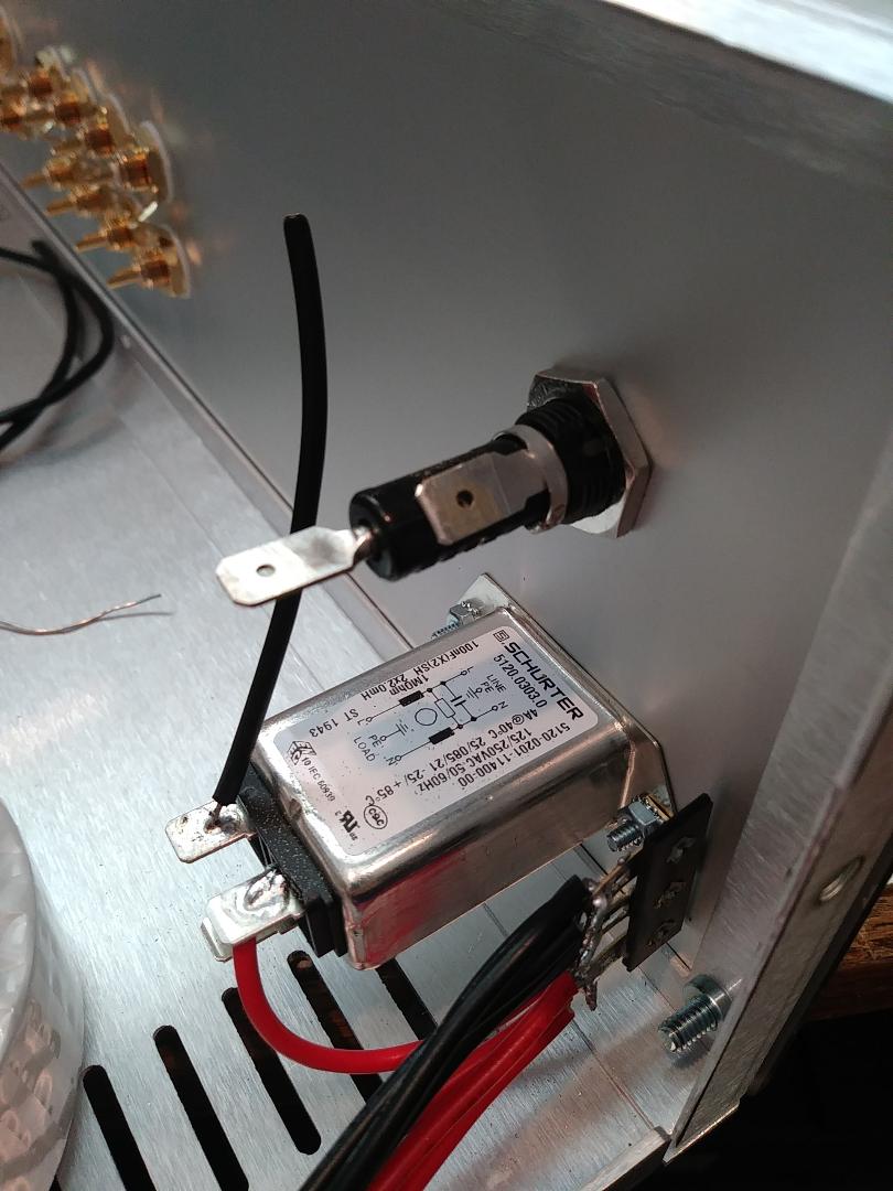
* use a file to remove oxidation on fuse leads
* connect a short red wire from the neutral (N) side of AC input filter to the bottom lug of terminal strip
* connect a short black wire from the line (L) side of the AC input filter to the back of the fuse holder
* connect one lead of the white twisted pair to the top lug of the terminal strip
* connect the other lead of the white twisted pair to the side of the fuse holder
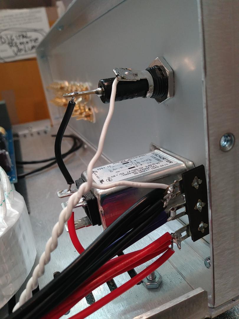
* connect the other end of the white twisted pair to the bottom and center terminals of the power switch on the front panel
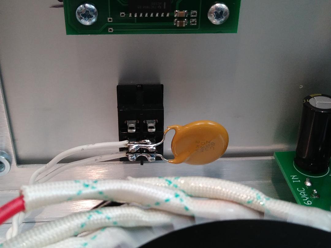
* solder the yellow X-Y cap across the power switch
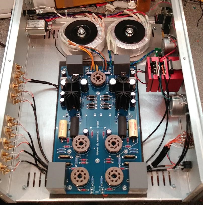
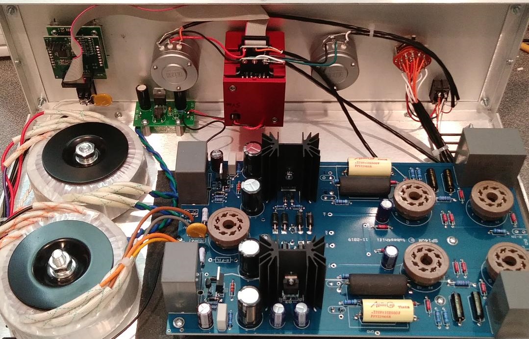
* trim the blue and green leads of the filament transformer to about 7" long
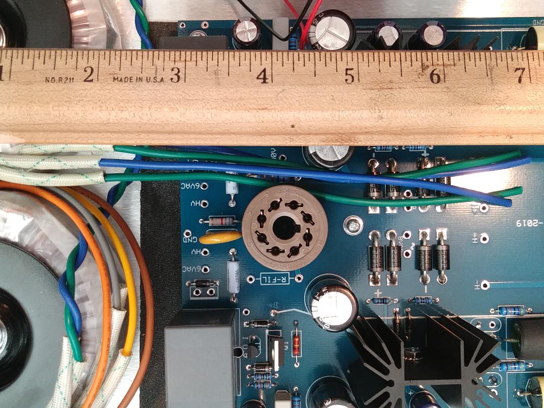
* tightly twist the blue and green leads together
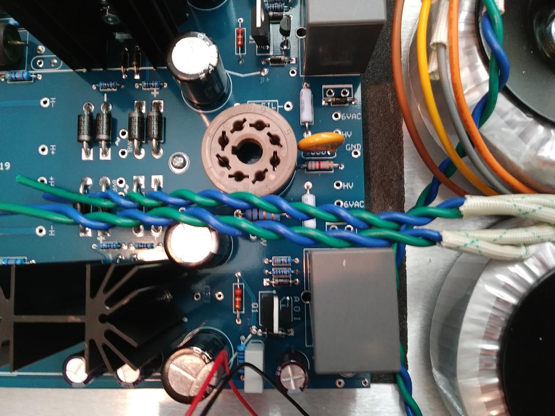
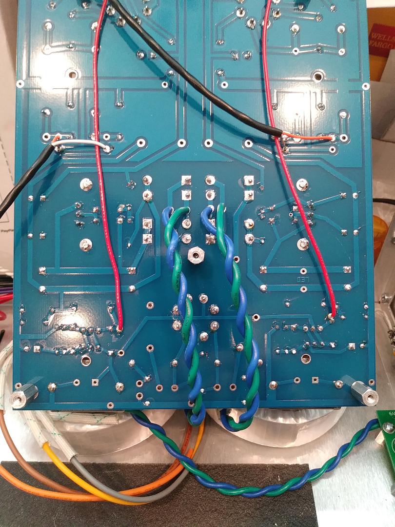
* solder the filament wires to the bottom side of the PCB at the 8VAC inputs
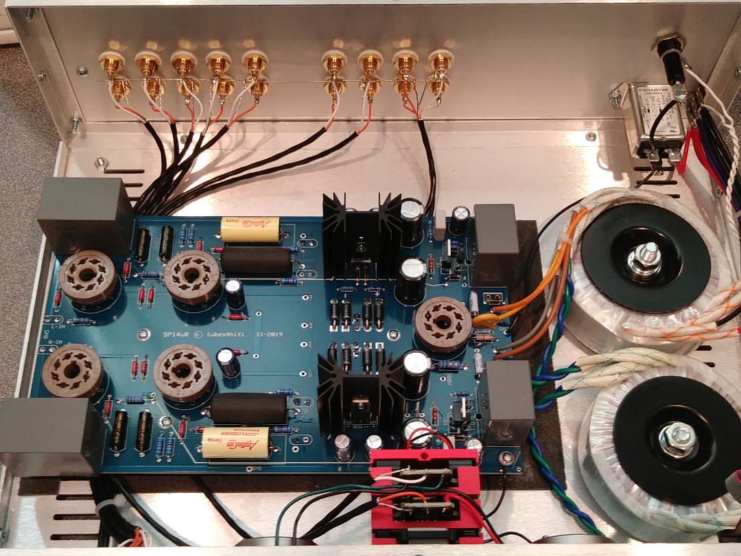
* a shield coax cable is soldered to the left and right outputs of the PCB (this one has both C3 (orange to OUT1) and C3A (white to OUT2) installed
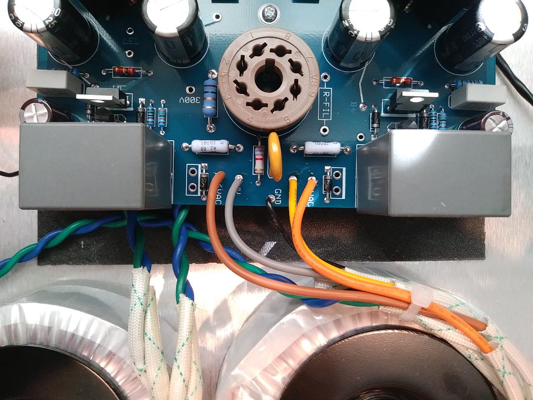
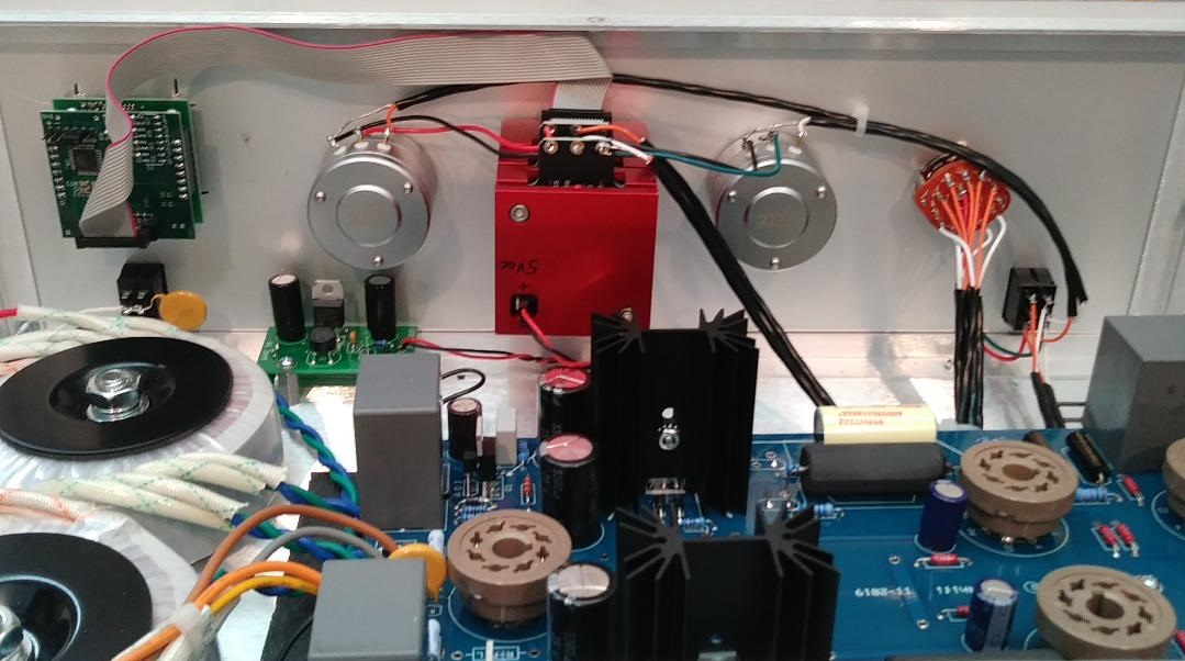
* wiring of main power transformer, brown and orange to 6VAC inputs, grey and yellow to HV inputs
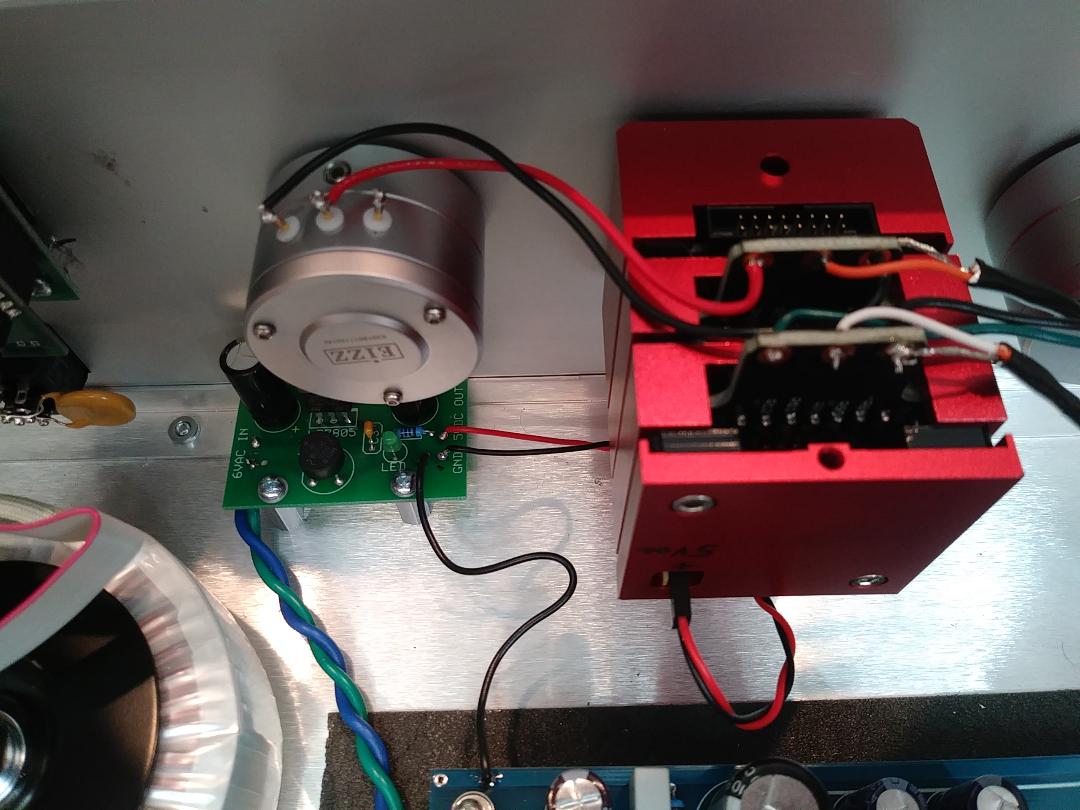
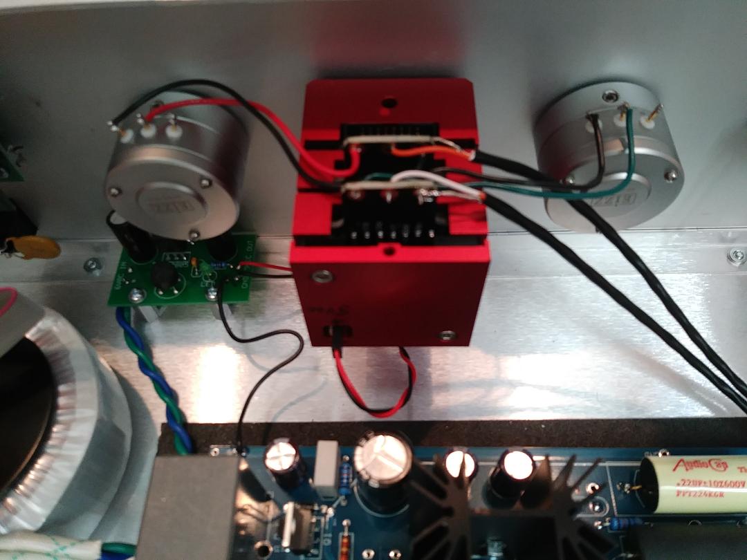
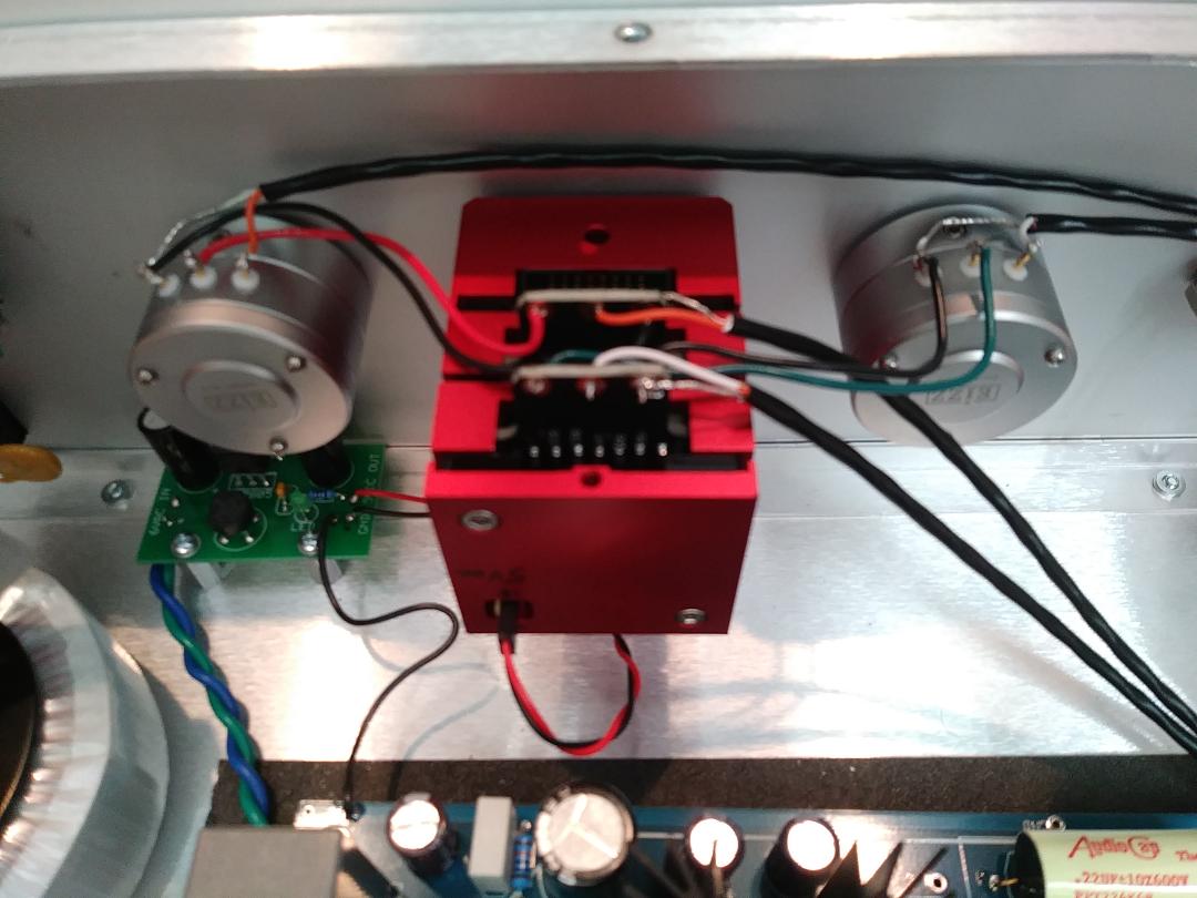
* blue and green twisted pair goes to optional Khozmo power supply for remote
* this photo shows the optional Khozmo remote power supply, the blue & green wires are 6vac from the large power transformer,
* the small red wire is 5vdc to the volume control, the small black wire is ground to the volume control
* the larger black wire connects the PS ground to the main PCB ground
* start wiring the right attenuator - black is ground (GND), center red is OUT to master volume IN (right channel)
* the left attenuator - black is ground (GND), center green is OUT to master volume IN (left channel)
* a separate coax for each channel, orange is RIGHT OUT to PCB RIGHT IN, white is LEFT OUT to PCB LEFT IN
* the coax shields connect to their left ground and right ground (separate grounds on volume control)
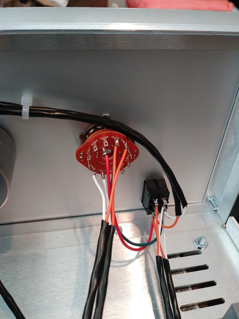
* a separate coax for each channel, from right channel attenuator OUT (orange) to the center terminal of SOURCE-TAPE switch (will connect in a later step)
* left channel attenuator OUT (white) to the center terminal of SOURCE-TAPE switch (will connect in a later step)
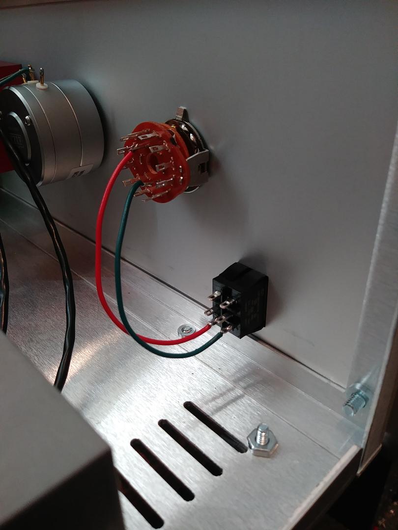
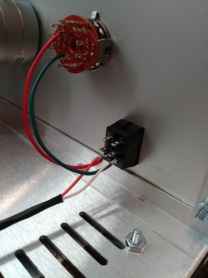
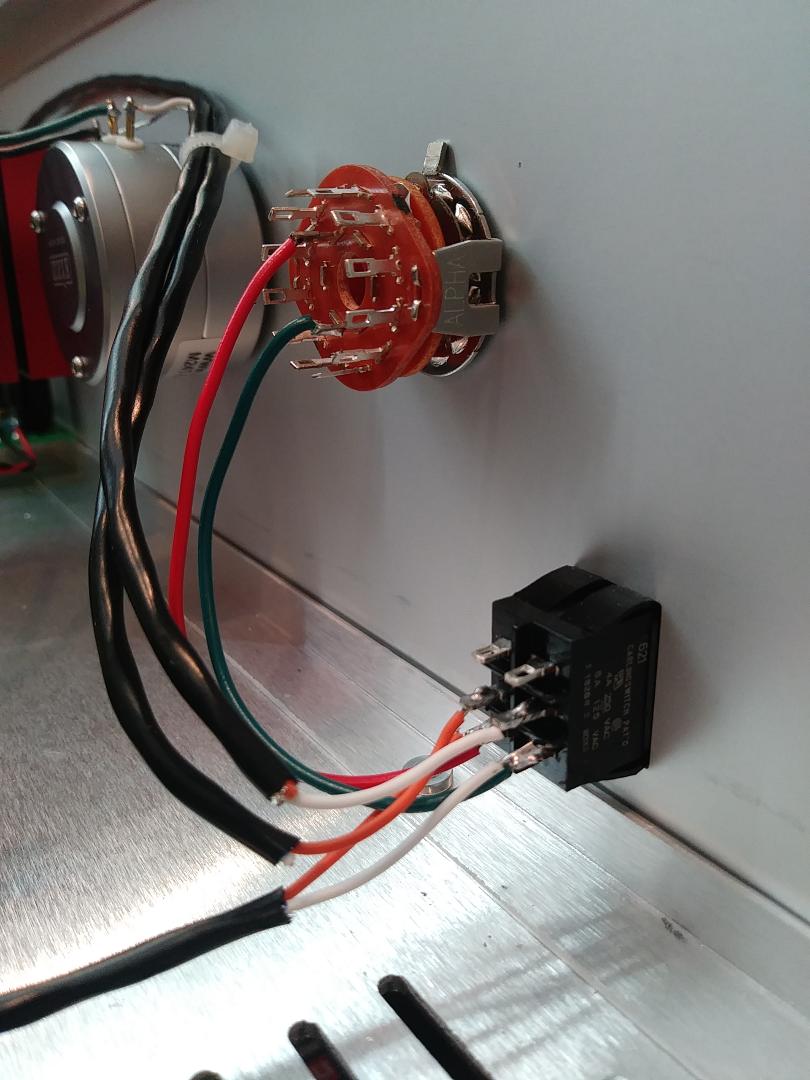
* RED wire is RIGHT channel out of selector switch, GREEN wire is LEFT channel out of selector switch
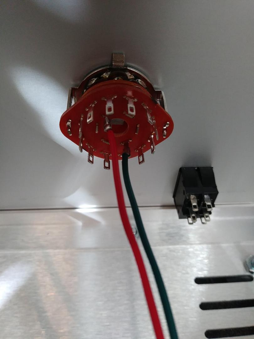
* connect selector outputs to bottom terminals of SOURCE-TAPE switch
* use a 17" long shielded coax to connect bottom terminals of SOURCE-TAPE switch to TAPE OUT (will connect in a later step)(shield ground not connected on this end)
* connect the shielded coax cables from the left and right attenuator inputs to the center tabs of the TAPE-SOURCE switch (shield ground not connected on this end)
* connect a 17" long shielded coax to the top terminals of the SOURCE-TAPE switch (this will connect in a later step to TAPE INPUT)(shield ground not connected on this end)
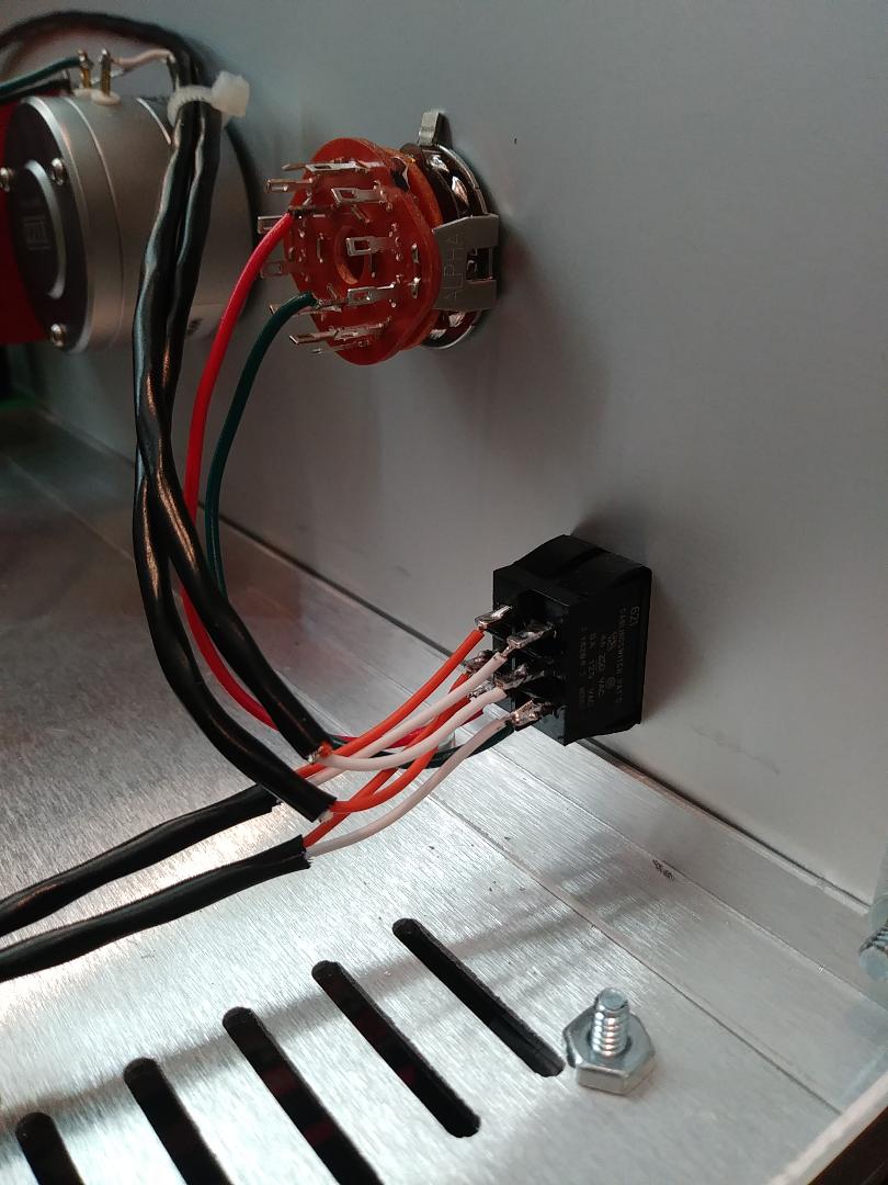
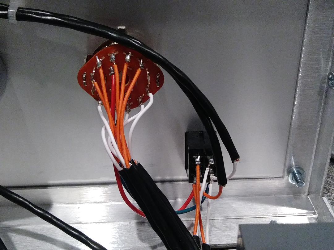
* cut 5 pieces of shielded coax 15" long, and connect to the inputs of the selector switch (right channel orange, left channel white, shields not connected on this end)
* the #1 input of the selector is usually marked with a black mark, found by rotating the front of the switch fully CCW), left channels are OPPOSITE of right
* this photo shows the #1 and #2 inputs wired
* photo shows top right orange wire is #1 right channel input, bottom left white wire is #1 left channel, connections are (CW from FRONT side of selector) for 2 thru 5 inputs
* front panel coaxes run under PCB to rear panel connections
* two coaxes from master volume out connect to PCB inputs left and right
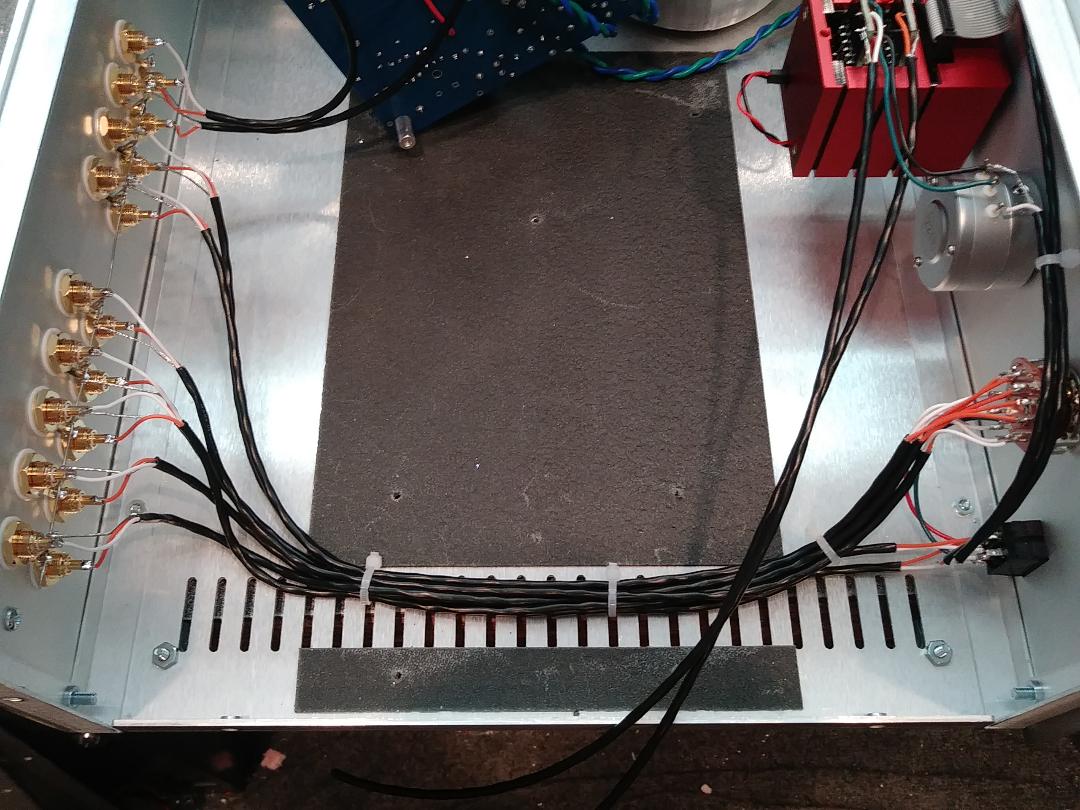
* front panel wiring is complete
* rear panel wiring - connect a solid wire to buss all RCA grounds together
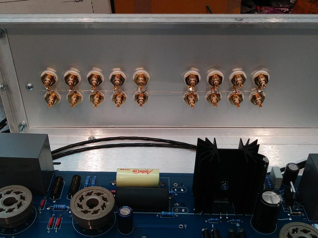
* TAPE IN and TAPE OUT connections are made with coax from front panel SOURCE-TAPE switch
* OUTPUT 1 and OUTPUT 2 connections are made from C3 left and right and C3A left and right
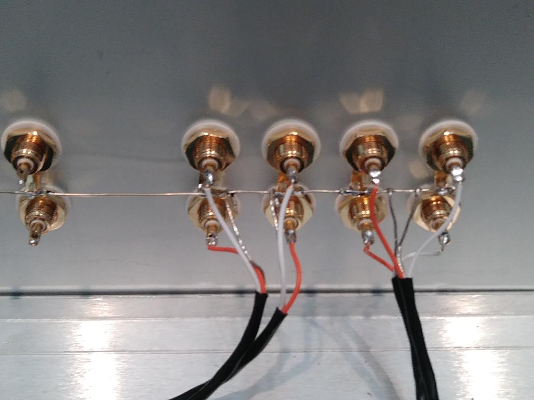
* rear panel wiring is done, back panel view
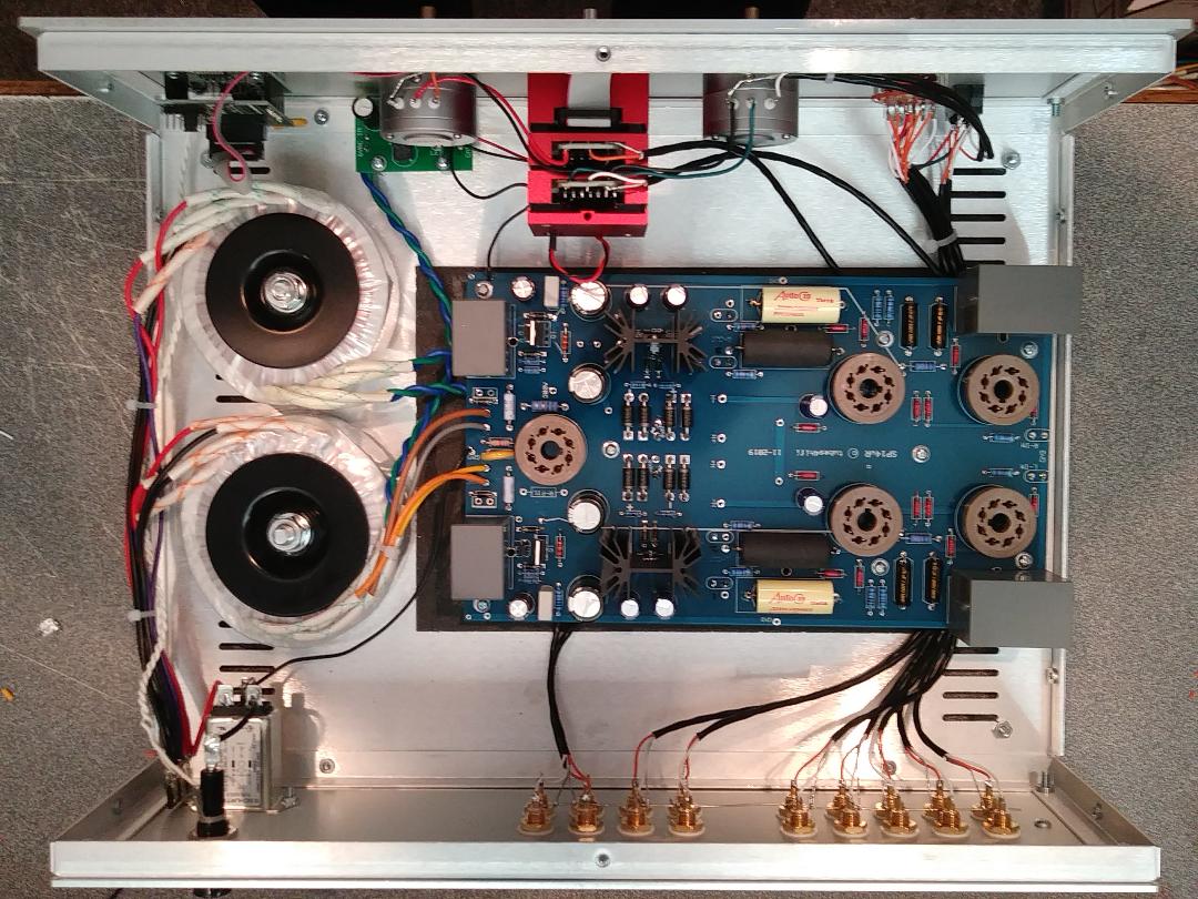
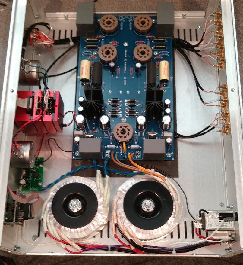
* preamp wiring is done (top view)
* end view
* front panel view
* other end view
here are some photos to help you identify the parts to build the SP14
inquire about any other options or modifications you might want via email . . . .
send email to ROY at: info@tubes4hifi.com
* connect one lead of the white twisted pair to the top lug of the terminal strip
* connect the other lead of the white twisted pair to the side of the fuse holder
* connect the other end of the white twisted pair to the bottom and center terminals of the power switch on the front panel
* solder the yellow X-Y cap across the power switch
* trim the blue and green leads of the filament transformer to about 7" long
* tightly twist the blue and green leads together
* solder the filament wires to the bottom side of the PCB at the 8VAC inputs
* a shield coax cable is soldered to the left and right outputs of the PCB (this one has both C3 (orange to OUT1) and C3A (white to OUT2) installed
* wiring of main power transformer, brown and orange to 6VAC inputs, grey and yellow to HV inputs
* blue and green twisted pair goes to optional Khozmo power supply for remote
* this photo shows the optional Khozmo remote power supply, the blue & green wires are 6vac from the large power transformer,
* the small red wire is 5vdc to the volume control, the small black wire is ground to the volume control
* the larger black wire connects the PS ground to the main PCB ground
* start wiring the right attenuator - black is ground (GND), center red is OUT to master volume IN (right channel)
* the left attenuator - black is ground (GND), center green is OUT to master volume IN (left channel)
* a separate coax for each channel, orange is RIGHT OUT to PCB RIGHT IN, white is LEFT OUT to PCB LEFT IN
* the coax shields connect to their left ground and right ground (separate grounds on volume control)
* a separate coax for each channel, from right channel attenuator OUT (orange) to the center terminal of SOURCE-TAPE switch (will connect in a later step)
* left channel attenuator OUT (white) to the center terminal of SOURCE-TAPE switch (will connect in a later step)
* RED wire is RIGHT channel out of selector switch, GREEN wire is LEFT channel out of selector switch
* connect selector outputs to bottom terminals of SOURCE-TAPE switch
* use a 17" long shielded coax to connect bottom terminals of SOURCE-TAPE switch to TAPE OUT (will connect in a later step)(shield ground not connected on this end)
* connect the shielded coax cables from the left and right attenuator inputs to the center tabs of the TAPE-SOURCE switch (shield ground not connected on this end)
* connect a 17" long shielded coax to the top terminals of the SOURCE-TAPE switch (this will connect in a later step to TAPE INPUT)(shield ground not connected on this end)
* cut 5 pieces of shielded coax 15" long, and connect to the inputs of the selector switch (right channel orange, left channel white, shields not connected on this end)
* the #1 input of the selector is usually marked with a black mark, found by rotating the front of the switch fully CCW), left channels are OPPOSITE of right
* this photo shows the #1 and #2 inputs wired
* photo shows top right orange wire is #1 right channel input, bottom left white wire is #1 left channel, connections are (CW from FRONT side of selector) for 2 thru 5 inputs
* front panel coaxes run under PCB to rear panel connections
* two coaxes from master volume out connect to PCB inputs left and right
* front panel wiring is complete
* rear panel wiring - connect a solid wire to buss all RCA grounds together
* TAPE IN and TAPE OUT connections are made with coax from front panel SOURCE-TAPE switch
* OUTPUT 1 and OUTPUT 2 connections are made from C3 left and right and C3A left and right
* rear panel wiring is done, back panel view
* preamp wiring is done (top view)
* end view
* front panel view
* other end view
here are some photos to help you identify the parts to build the SP14
inquire about any other options or modifications you might want via email . . . .
send email to ROY at: info@tubes4hifi.com
|
| |
|
|